
VELOCITY COMPOUNDING OF STEAM TURBINES

In this method, there are number of moving blades (M.B), separated by rings of fixed blades (G.B) , Keyed in series on a common shaft. The stem from the boiler is passed through the row of  Nozzles from  the boiler pressure to condenser pressure and attains high velocity.
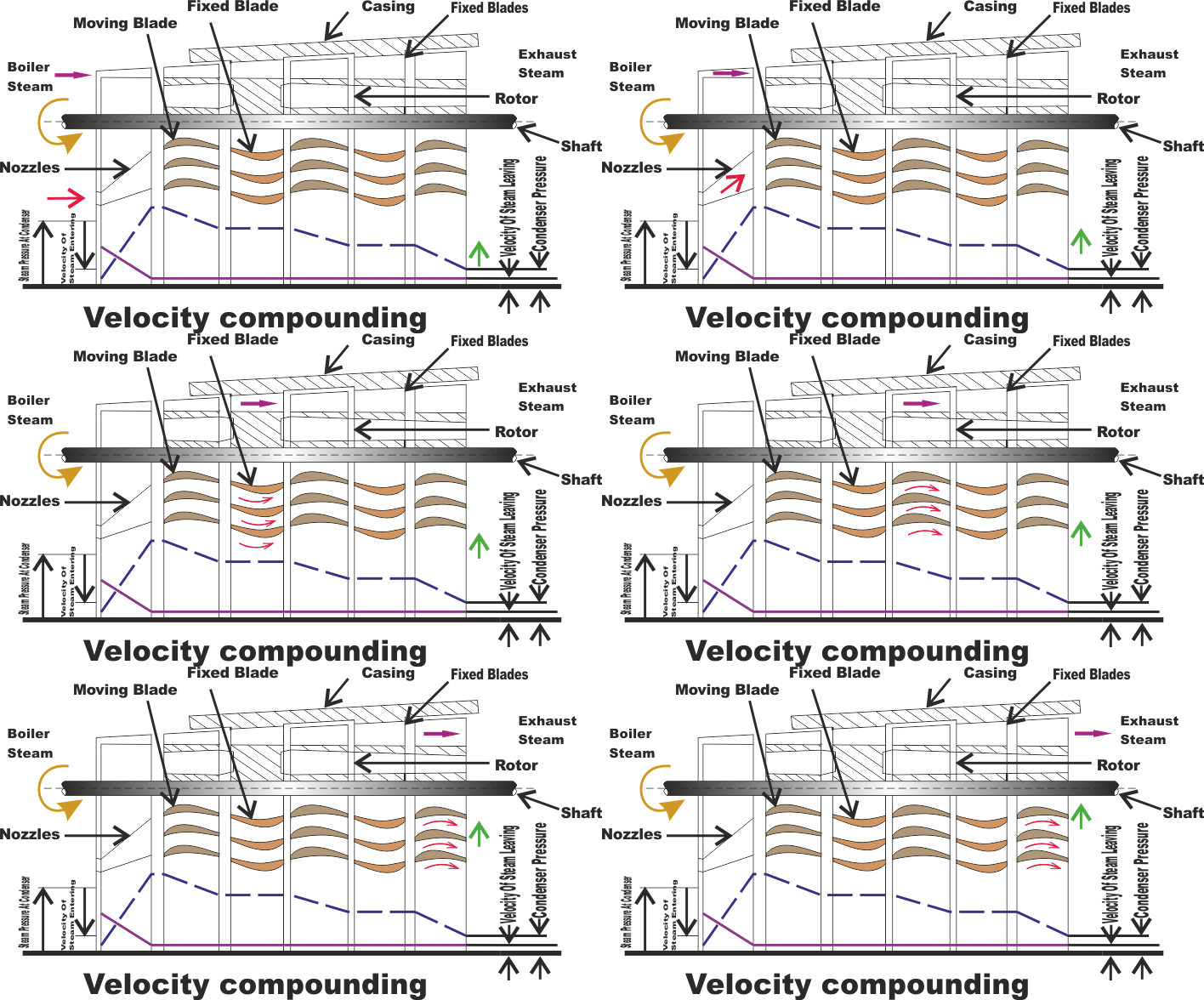


 The high velocity steam jet passes over the rings of moving blades and fixed blades alternatively. During   which, a part of kinetic energy is absorbed in each ring of moving blades. The direction of  steam is   changed without altering much its velocity in the rings of fixed blades. Thus, all the Kinetic energy is utilized in moving blades. Since there is no pressure drop as the steam passes over the moving blades, the   turbine is thus of impulse type.

 The pressure drops fully at the nozzle itself and the pressure is kept remains constant in moving blades   and fixed blades. The velocity of  the steam coming out of nozzle is very high and it is reduced in stage  -   by - stage of moving blades. Hence, it is known as velocity compounding. The velocity of steam is   constant while passing through fixed blades. 

 Example of  this type of turbine is low. A three rows wheel is used for driving small machines. It may   be noted that a two rows wheel is more efficient than the three row wheel turbines.

 Advantages :

* Its Initial cost is less because of few number of stages.

* Less space is required.

* The System is reliable and easy to start.

* There is need of strong casing due to low pressure.

 Disadvantages : 

* Frictional losses are high due to high initial velocity. Hence, the efficiency is low. 

* The ratio of  blade velocity to steam velocity is not optimum for all wheels. It also reduces the efficiency.

* The Power developed in later rows is only a fraction of the power developed in the first row. But, the space requirement of all the stages is still the same. This increases the cost and material requirement. 

Comments

Popular posts from this blog

ELECTRICAL COMPARATORS AND ITS WORKING

Electrical Comparators are used as a means of  detecting and amplifying small movements of a work contacting elements. An electrical comparator consists essentially of  a pick-up head or transducer for converting a displacement into a corresponding change in current and a meter or recorder connected in the circuit to indicate the electrical change, calibrated to show in terms of displacement. Generally, an amplifier is needed to provide the requisite sensitivity and to match the characteristics of different parts of  the circuit. Electrical comparators can be classified according to the electrical principle used in the pick-up head. Most of the comparators use either a differential transformer, an inductance bridge, a strain gauge or a capacitor as a means of detecting movement of the gauging element. There are different types of  electrical comparators. One kind called an electrolimit gauge is used to check or measure the outside diameter of a  roll. The objec...

TOP POLLUTION RECORDED IN WORLD

CHERNOBYL NUCLEAR DISASTER (NUCLEAR POLLUTION) :  In April 26,1986, the melt down of the Chernobyl nuclear reactor , in Russia, has leaked out the radioactive rays and radioactive materials.   Effects : 1. In this Pollution nearly 2000 persons have been killed by the accident. 2. People suffered due to the illness such as, degeneration of the cells, severe bleeding, anemia, skin cancer. 3. Animals, Plants are also affected by nuclear radiation.  MINAMATA EPIDEMIC (1953) : MARINE POLLUTION ( CASE STUDY ) Minamata is a small coastal village in Japan. The Chisso Chemical Company , which produces vinyl polymer plastics used organomercurial compound. The industry released its effluent into Minamata sea. The effluent containing mercury ions is converted into methyl mercury, which is highly toxic.  The marine organisms like phytoplankton and zoo-planktons easily absorb the toxic methyl mercury compound. These organisms are consumed by small fishes and these are in ...

MELTING FURNACES FOR FERROUS METALS : CUPOLA AND ITS WORKING

Various types of melting furnaces are used in different foundry shops, depending upon the quantity of metal to be melted at a time, and the nature of work that is carried out in the shop.  The primary objective in cupola is to produce iron of desired composition, temperature and properties at the required rate in the most economical manner. Besides, this furnace has many distinct advantages over the other types, e.g., simplicity of operation, continuity of production, and increased output coupled with a high degree of efficiency.  Description Of a Cupola : The Cupola Furnace consists of a vertical, cylindrical steel sheet, 6 to 12 mm thick, and lined inside with acid refractory bricks or acid tamping clay. The refractory bricks or the tamping clay used consist of  silicon oxide acid (SiO2) and alumina (Al2O3). The lining is generally thicker in the lower where the temperatures encountered are higher than in the upper region. The shell is mounted either on a brick work fo...